Build this Joystick! Function and Code. Last update 11 04 23.
I repeat a little from the main description:
The principle is to use the earth gravity field to monitor the position of the hand controls. To cancel out the effect of tilting the whole box a
third accelerometer is attached to the box. The signal from this is subtracted from the accelerometers attached to the controls.
Data is gathered by the use of two 8 channel ad converters. The process is controlled with means of the Parallax propeller microprocessor.
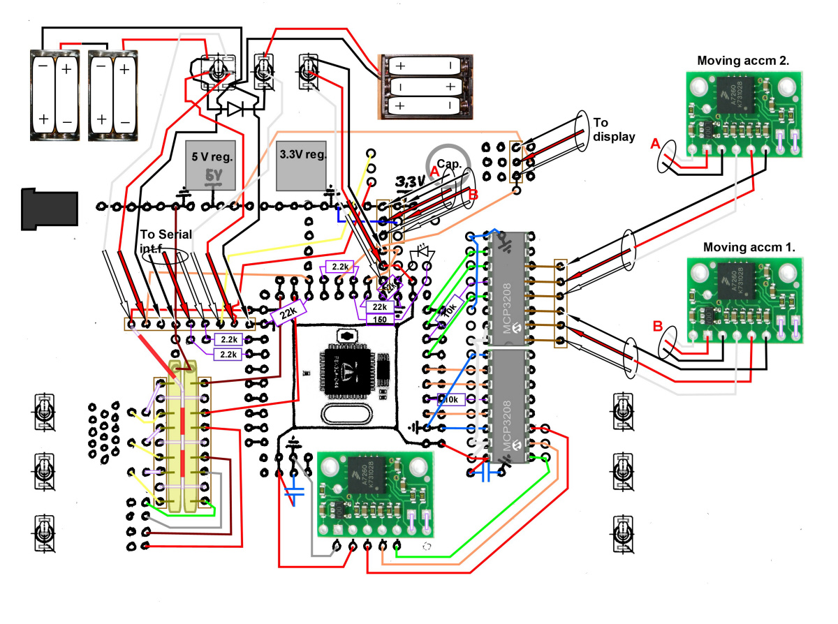
Circuit scheme and PCB layout.
The scheme is the same as presented under electrical buildup section.
Important note: The accelerometers shall all be placed in the same direction physically (with controls in neutral).
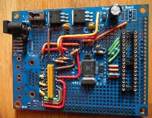
The parallax propeller proto board is used as a base. Do also download the proto board scheme from the parallax home page
(found in a PDF describing the proto board)!
The led is not actually needed. It indicates that things are running. It can be excluded after running up.
Code: I have to apologize if found any Swedish words in the code. I do some of the coding in my native language and there may be some
words left. I also have to apologize for any bad grammatics.
The main code has the name: JoystX2_sov_newgen2
The main code governs several pieces of called for code. Some of those are specially written for this application and other are just cut
down parallax and other objects. Here is a list of these object with links so you can see and download them. They are both presented in
txt and spin format. You may be able to read the spin format in the same way as the text format, I think that depends on the browser.
Otherwise you need the Parallax propeller tool interpreter to be able to read it.
Anyway, to use and program your processor you will need the parallax propeller software.
JoystX2_sov_newgen2.txt spin: JoystX2_sov_newgen2.spin
Debug_Lcd_min_ver.txt spin: Debug_Lcd_min_ver.spin
FullDuplexSerial_mini.txt spin: FullDuplexSerial_mini.spin
recieve7.txt spin: recieve7.spin
Sandadata.txt spin: Sandadata.spin
Simple_Numbers_mini.txt spin: Simple_Numbers_mini.spin
Also needed for calibration:
JoystX2_sandafp_debug.txt spin: JoystX2_sandafp_debug.spin
There are more objects called for in the code, these are standard objects delivered with the software coming with the propeller start kit.
They can also be found on the Parallax homepage. The only exception is the BS2_functions_fast object. It is the same as BS2_functions but
with the only change that the waitcnt in the shiftin and shiftout PUB:s are changed to 500 instead of 1000. That’s why its called "fast". You
may use the original BS2 object but the code will be slower. On the other hand this change may affect the saturation of the ad-conversion.
This could produce slightly less accurate values. However I think this is of low importance as about the same fault will go into every value so
that after computing the angles (see below) the fault will be cancelled out.
So now lets discuss the code a bit:
As usual the code is in the spin language.
The first part mainly consists of gathering data from the ad-converters. 9 channels are needed so there is need for two ad:s. Consequently
there will be 7 channels left. You may find some way to use them if you wish so. One suggestion is to connect two potentiometers. These
could produce a command to regulate lamps on your project (maybe using the same type of control circuit as for your motors).
This first part of code was inspired by a code made by Bryan Kobe in June, 2007. It was then called AD channel debug. It was
found on the Parallax homepage. I’m very thankful to him as I think this part of the code is a great part of the real kernel and is
good written.
After that data are filtered by simply making mean values. Here 10 consecutive data is used. This could be higher producing slower but more
soft response.
Arc tangents are then computed for x and y directions with respect to z. This is a measure of the inclination of each accelerometer. The same
computation is made for all three accelerometers. The value from the box-fixed accelerometer is subtracted from the other values. The result
will be the angle of each control arm.
The result can then be used to steer a motor, motors or other things of your choice.
Here the code is adapted for use with 4 motors. The variables
MH ' Command to x-engine right
MV ' Command to x-engine left
MVH ' YZ engine command right
MVV ' YZ engine command left
found in the code will hold values to send out to your vehicle.
This is performed by the object "sandadata". The function must use positive integer values 0-255 so commands are conditioned to always be
positive. The exact value "255" is used as a sync signal and cannot be used as motor command.
If you look pretty far down in the code you will find the sending out sentences.
There is also send out a mode data (called mode). It holds a figure 0 to 7 which I have used to steer a total gain command for the motors and
a command to steer which light to use and not.
The "sandadata" object is set to use pin 16 as output channel. In the scheme it is also protected by a 2.2kohm resistor.
You will need to calibrate your new joystick.
There will be a tare when reading from the ad:s. You will for example find following rows in the code:
accx:= (accx-zero + 250)*-1
accy:= (accy-zero + 665)*-1
accz:= (accz-zero)*1
where the figures 250 and 665 are adjustments made to get a zero reading when the box is horizontal. The tare will differ depending on
variations in make of the accelerometers and differences in the ad:s. There is also the effect coming from accelerometer not mounted exactly
parallel to card.
To adjust the tare there is a debug variant of the main code. This is called
JoystX2_sandafp_debug.spin
You have to load this variant at first and after finding the right tare reload the processor with the fully functional code updated with your own
tare.
The debug object is started with the following rows in the debug code:
debug.start(9600) ' start terminal, will by default (see obj debug) use pins 30 and 31
debug.str(string(FF, "Joyst Channel Debug med 9600 baud", CR, LF, LF))
debug.crlf
Not to send to many data to fast there is a counter boink2 that makes the code only send debug data every fourth loop. The code will send
debug information on the readings to a PC terminal window.
You will find rows like:
debug.str(string("accxm, accym, acczm="))
debug.str(num.ToStr(accxm, Num#dec))
debug.str(string(" "))
debug.str(num.ToStr(accym, Num#dec))
debug.str(string(" "))
debug.str(num.ToStr(acczm, Num#dec))
debug.str(string(" "))
debug.crlf
debug.str(string("Roll*100="))
and so on…
These are commands to write variables in your PC-window like accxm and its value. You may ad your own sentences to the code to read
other variables of your interest.
Now: adjust the tare so that the readings of each motor command will be about 127 with controls in neutral position. Begin with adjusting the
tare of the board mounted accelerometer so that the readings of accxm and accym will be within zero +/- 20. N.B! The box must be absolutely
horizontal doing this! The readings will vary a little caused by small disturbances, maybe jumping up and down some ten counts. The value of
acczm will have a high figure, something 4500 and shall be so.
After finding the tare; write the figures down (six different values) and transfer them to your full functional code (JoystX2_sov_newgen2.spin).
Now back to the fully functional code:
The code has a function for reading back data from your vehicle. It is performed by the "recieve7" object. The object starts a new cog in the
propeller processor. (se propeller processor documentation). Anyway this represents a stand alone parallel process.
In my case I read back magnetic heading and depth data from the vehicle. The figures are used to compute correcting data: "headdiffa" and
"depthdiffa". The correcting data can also be conditioned in different ways by switches. The correcting data is passed over to the main cog
(computing process) via pins 10 and 12. In the main process it is used to correct heading. (I do not use correcting data for depth momentarily
due to bad temperature stability in depth pressure transducer). In the code will also be found switch inputs for "zero" adjust of heading and
speed. This enables for adjusting for example speed to a certain level without hitting the joystick arm. Can be good for long transport rides.
Those variable are denoted "-tick".
The "recieve7" object do also send vehicle data to the LCD display. Here I think the parallax description of the LCD and driving routines is
the best reference. The object in my code is called "Debug_Lcd_min_ver" but is mainly the same thing that can be found in Parallax
documentation with small changes. In the code the standard speed of 9600 baud for the communication with the display is used. The
speed has to be set (with the small switches) on the display back side.
In the code there is a startup sequence for the display. It will show the name of your project and a small cat. I think it is rather obvious
how to change the text. To alter the cat face I refer to the Parallax documentation on the display.
Now don’t be afraid to experiment with the code!
Johan
Back to Joystick start page
Electric description Mechanics description
Back to ROV main page