The Sea Lion
mellaApr. 2012 update. Links revised.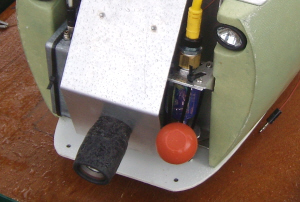
General description in current page
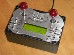
Build your own joystick The microprocessorHere I would like to present a small project I have done. It is a small remotely operated submarine. It utilises the propeller chip to collect information on depth and direction. Two more propeller chips are used for steering. One placed in the joystick as described here:
. Joystick And one placed in the submarine used to control the parallax 25A motor control units.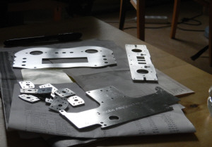 Buy! Joystick sheet metal kit.
Retrospective:
When I started this project I used relays for control of the submarine. The reason was simplicity. With relays it is simple to control the motors without extensive power loss. Power loss means heating of control system and that can be a problem within a closed box. The system was build on the principle of combining motors in series and parallel. By means of low value resistors additional adjustment of motor speed was achieved. (OK, resistors mean power loss but with low value and well sized it will work). Relay manufacturer Omron has simple serial interface to control relays by two wires. This was used to control 15 relays allowing for among other functions 5 different motor speeds forward and backward. I still think relays can be a nice principle to start with in this type of project.
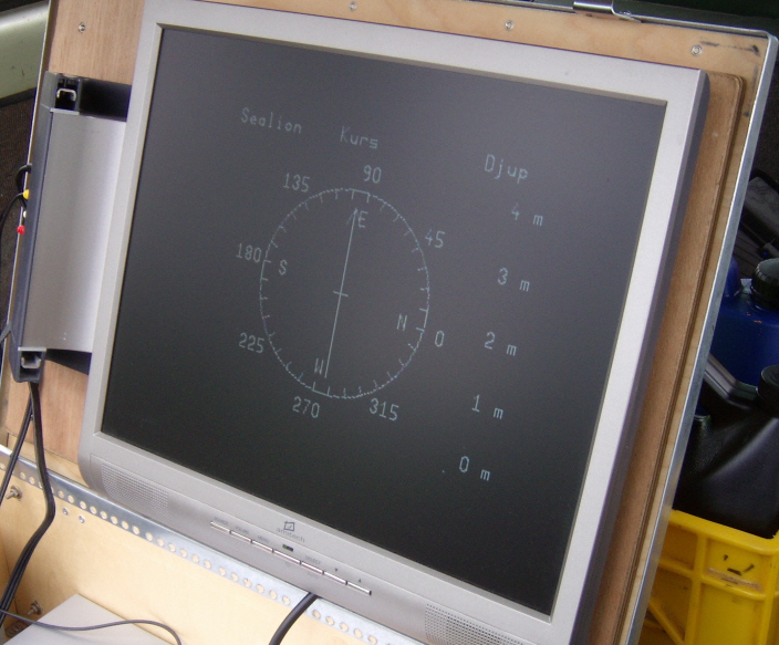
Having used this construction for a couple of years I started the construction of a new joystick. Based on a microprocessor. This allows for a much more exact steering and coupling of measured data (depth, heading etc) to access auto pilot control of the submarine such as lock of heading etc./
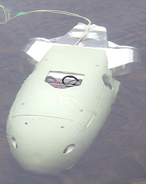
The submarine performs pretty well and has a good operating time estimating at least 2 hours powered on an ordinary car battery. It is equipped with a TV camera for underwater pictures.
Main dimensions:
Length: 120cm, width: 60cm, height: 35cm. Weight about 50kg. . Supplementary data
 . Film sequences.
Data acquisition:
For the depth data a circuit from Sencera called SPD-015-G-2 is used. It is mainly intended for medical purposes like measuring blood pressure but is also made in a version with suitable pressure span for this application. With a max pressure of 15 psi it will be good for a depth of about 10 meters or 30 feet. It measures absolute pressure and the "backside" of the internal cavity is connected to the surrounding which means that it has to be mounted inside a cavity isolated from the water pressure and a hose has to lead the pressure to be measured (i.e. water pressure) to the intake of the device. The device can not handle direct water contact why this hose has to have some sort of aneroid or balloon in the other end. I used a type of rubber ball intended for flushing children’s ears and can be bought at any pharmacy here in Europe.
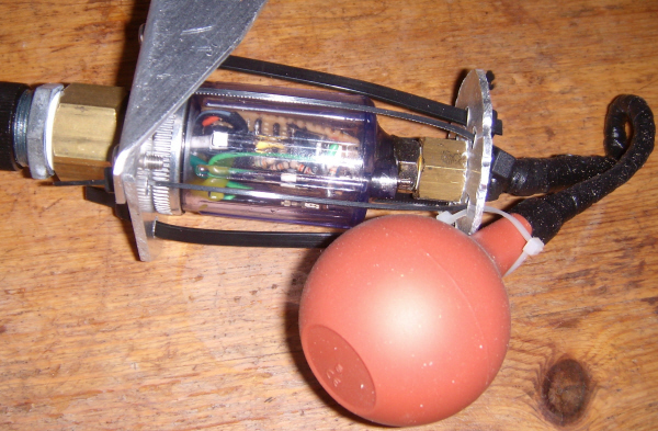
The cavity is simply a water dissolver for pressurised air. It seemed suitable because of its low prize and the visibility it provided the main part made of clear plastics. It also has good sealing and has convenient NPT threading. One of the internal bolting had to be taken away why the external straps. (remember that the water pressure working on the cavity is coming from outside why the strapping will not be heavily loaded). Inside the cavity are placed the pressure sensor, a quadruple op-amp and some resistors. The disadvantage of this construction is its poor temperature stability. The pressure sensor itself is temperature sensitive and the rubber balloon with its air content will be temperature sensitive. The construction could be improved by some temperature sensitive resistors. A better way may be to buy some other device more adopted for the purpose. The reason why I build this device was it was fun and I learned a lot about op-amps and ad-converters. The op-amp used was LMC660 and the ad-converter ADC0831.
To find out the heading I would recommend to use a circuit of type LSM303DLH. It is pretty low cost and can be found mounted on a break out board LSM303 found at Spark fun electronics. It consists of two types of sensors, magnetic sensors and accelerometers. It measures magnetic field divided in directions relative to the sensor. And it also measure acceleration so that the inclination of the sensor relative to horizon can be detected. These two information’s are needed to compute an accurate magnetic heading. This can be done with your parallax propeller microprocessor.
You can also use two circuits provided by Parallax: The HM55B and H48C. At their downloads page can be found the following:
http://obex.parallax.com/objects/399/
It holds a description for use of these components and code.
A third alternative is the HMC6343 from Honeywell. This is a solid-state compass module with tilt compensation and internal software which provides you with readily calculated heading over an I2C interface. It is however a lot more expensive.
To start using the propeller microprocessor I recommend you to by a start kit. It holds programming tool, experiment board and documentation. There are also many useful objects (programs) included.
Good luck!
Johan
Questions?
You can e-mail me at info@ancker.org
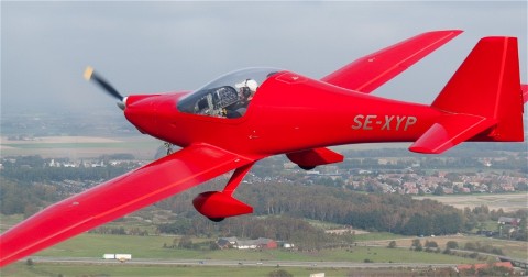 This site holds an interesting aircraft!
  http://www.nordevall.com/se/gazeti/1/hem
IMPORTANT!:
The author does not take any responsibility for that here presented information is free from faults. You build at your own risk and have to be careful testing the equipment. If any harm to people, living creatures or other material would arise the author don’t take any responsibility for this. This applies to both hardware and software. In no event shall the authors or copyright holders be liable for any claim, damages or other liability, whether in an action of contract, tort or otherwise, arising from, out of or in connection with the software or the use or other dealings in the software.